This lecture discuss about the details of Operational Amplifier. Operational Amplifiers were used in analogue computers. Almost all analogue devices uses, operational amplifiers. It is used widely in electronics industry.
This topic limit our discussion to the op amp usage as a circuit element , how ever this discussion does not tells us about any knowledge that how op Amp is made or how it is constructed, or what is happening inside the chip. In general an Op Amp is made my connecting many transistors in particular configuration .
Basic Structure Of Op Amps
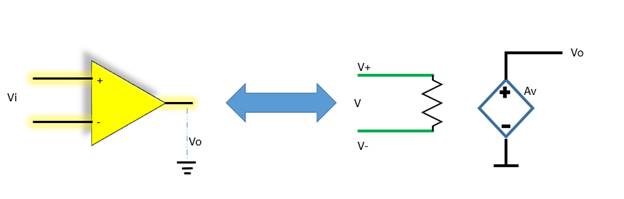
Instead of going for a circuit description , we can go for a abstraction of a op Amp. An abstraction is a representation that tries to model a complicated phenomenon , easily .
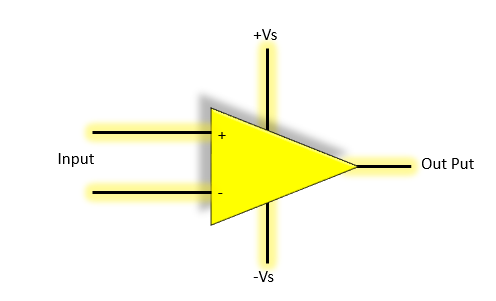
The operational amplifier has two inputs , one positive and other negative , in which voltage signals are applied , and than we have an out put terminal

One needs to clarify that these out puts and these input are taken as with respect to some ground… So there must a be a ground. As ground is a must part, of this IC , so we don’t show it as a part of input or output .

As with any IC the op Amp has also power supply , The Op Amp has two Power supplies, one is positive power supply +Vs, and other is negative Power supply –Vs
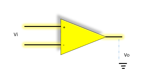
One more abstract representation of Op Amp is below, where we do not show the ground line or power signals. It is easy to draw and represent
Working Model
If we summarize the Op Amp circuit , we may end up in following components
1. Positive Input V+
2. Negative Input V-
3. Out Put Vo
4. Voltage Controlled Voltage source, which controls the output of a signal
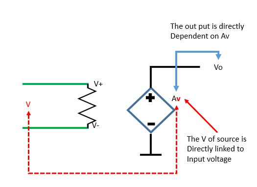
A model can be drawn to represent it

The Voltage Source
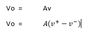
Now Av is a voltage controlled voltage source, which determines the output of voltage. This source is depended on the input voltage V, which is equal to 
Normally the gain is in 106 Power . It mean if the input signal is 1 volts and the gain is 1000, the output voltage will range from 0 to 1000 Volts.
The Out Put
So as Vo is directly linked to Av , so out put can be written as
The Input
The both input signals of op Amps are connected together, through a very high resistance. Due to this high resistance , the current i+ entering V+ , and i- in v- are very small or almost equal to zero . In a practical op-amp the input current is in the order of pico-amps (10−12)amp, or less.
Amplifier
An amplifier is a circuit that has an ability to amplify the input wave form

THE IC
Op Amp is available in market in integrated circuits They range in cost from a few cents to many dollars, depending on the specs. These specifications include input impedance, input bias current, output offset voltage, external power requirements, etc

Below is internal diagram of the op Amp IC . The pins are numbered counter-clockwise from the top left . Where the dip shows , where the pin 1 is located

Building Circuits with operation Amplifier
During the previous discussion we have already determined that following two circuits are equivalent